Summary
Cadence Tracker Sim showcases how using a single inertial measurement unit on a
patient’s elbow can be used to form trajectories of a prothestic arm.
The inertial measurement unit(IMU) is used to capture accelerations on
the elbow of a patient. These accelerations are utilized to derive what activity
the patient is performing. Further, if the patient is walking, ground reaction
forces captured by the IMU will imply a step cadence. Finally, a trajectory is
crafted such that the apex of the arm swing matches the step cadence.
Software
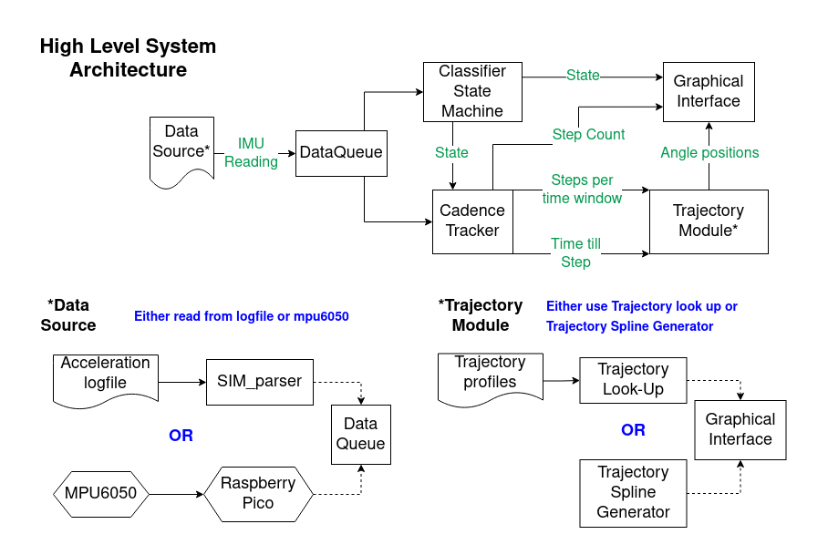
There are five major software modules used for this process. The IMU interface
device responsible for capturing acceleration on the patient’s elbow. A
classifier state machine that can identify if the patient is walking or not. A
cadence tracker that counts the number of steps taken, predicts when the next
step will take place, and estimates a notional walk speed. A trajectory module
which uses the walk speed and current angles to output a desired angle.
Lastly, a graphic interface to showcase the arm’s motion via a single or double
pendulum.
IMU Interface
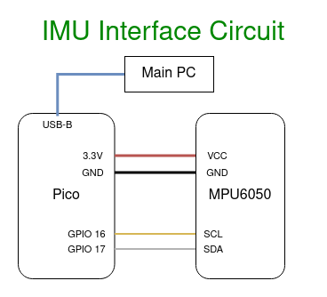
The IMU interface is a circuit composed of a raspberry pico communicating to a
mpu6050 via an I2C protocol. The first messages sent during initialization
write to configuration registers of the mpu6050 to set the sample rate and the
fidelity of the sensor’s measurements. Both the raspberry pico and the mpu6050
are set to read and produce data at 100Hz.
To read the acceleration, the raspberry pico sends a request to receive the
acceleration data, which is returned at six 8-bit integers. The pico then
converts integers into three floats representing the x, y, and z component of
acceleration. After the conversion, the value are sent to the main device.
Below is a circuit of the raspberry pico connected to the mpu6050
Classifier State Machine
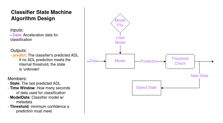
The classifier state machine reads a small snippet of acceleration data
to determine which activity that data represents. Three features are derived
from the acceleration data and placed into a k nearest neighbors(KNN) model to
determine the activity. The features we use are the dominant frequency of the
data, the signal power or intensity at the dominant frequency, and the entropy
of the frequency transform of the data.
The classifier’s training process takes a collection of logfiles and shreds them
into small fragments roughly two to three seconds long. These fragments
represent the input into the KNN classifier. From each fragment, we acquire the
three features and assign the fragment a label representing the activity being
performed at the time. These new features are collected into a feature set,
a collection of points in the feature space with assigned labels.
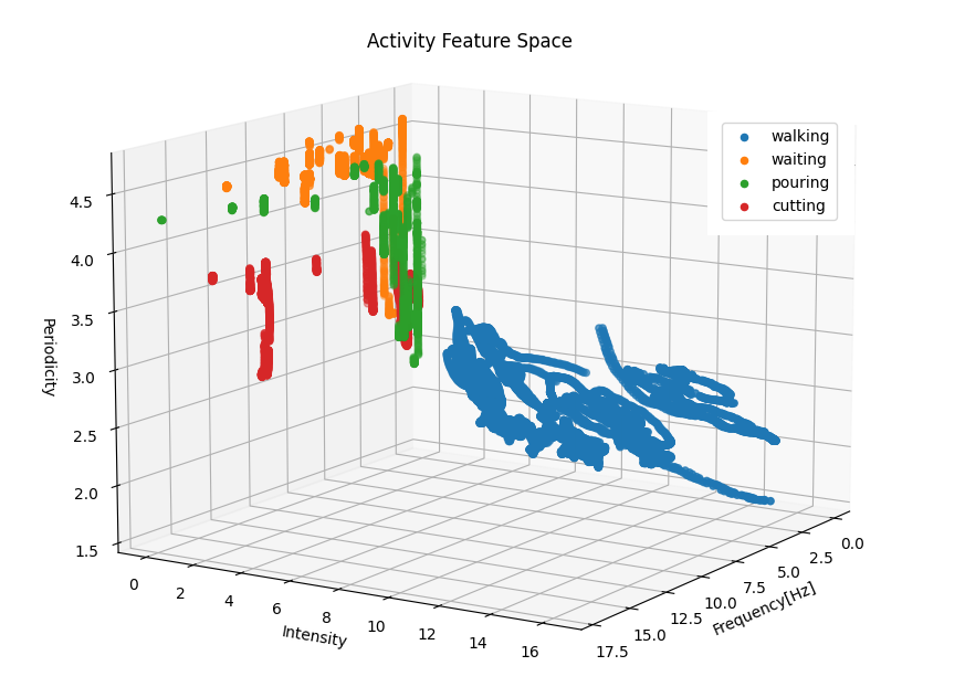
During execution, a KNN classifier takes an input of acceleration data, extracts
the features and, plots this new point in the feature space. It then compares
the k closest neighbors to the new point to provide a classification of what
activity the input represents. We chose a KNN classifier because: (1) the
algorithm is fairly lightweight at values of low k without sacrificing
accuracy and (2) the classifier is amorphous, i.e. it makes no specific
assumptions about the structure of our data. Conversely this means the knn
does not take advantage of the time-series structure of our data, but it
supplements this disadvantage but expanding the range of label behaviors. For
example, different gaits from patients of all ages can fall into the ‘walking’
label despite the different patterns they present
Cadence Tracker
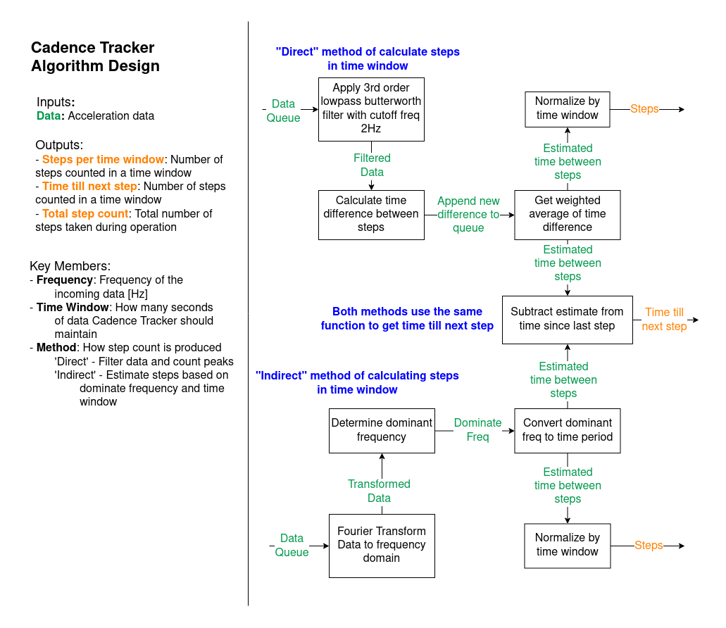
The Cadence Tracker is responsible for counting steps, predicting the next step,
and estimating a walking speed. In order to count the steps, the Cadence
Tracker calculates the acceleration magnitude and applies a low pass
third-order butterworth filter with a cutoff freq of two hertz. The Cadence
Tracker then finds the peaks and valleys to determine the initial number of
steps and adds to it whenever a new step arrives. Below is an example
where I’m walking at 1.0 m/s for about 30 seconds.
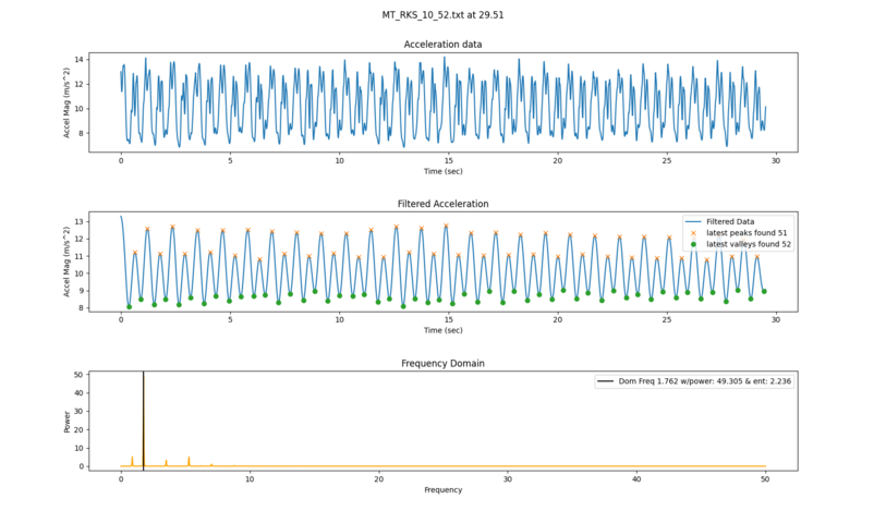
For this example, the cadence tracker was given logged accelerations at 100
hertz. The tracker waits until it’s time window (typically 3 seconds) is filled
with data, then identifies how many steps have already taken place. After that
it increments the step as new peaks are found. The first subplot shows the raw
acceleration magnitude signal feed into it and
the second plot shows the filtered signal with the tracker’s guess at the peaks
and valleys.
In order to predict how long until the next step appears, the Cadence Tracker
has two available options called the ‘direct’ method and the ‘indirect’ method.
The ‘direct’ method counts the number of steps and how much time has passed
between them. It maintains a history queue of time between steps and takes a
weighted average to determine an average time difference. Then it tracks how
long it has been since the last step and returns the remaining time.
The ‘indirect’ method calculates the average time difference by examining the
dominant frequency in the current time window. By taking the reciprocal of the
dominant frequency, finds the average time between each step. It then follows a
similar approach to get the remaining time until the next step. The plot in the
above image shows an example of grab the dominant frequency.
These average time differences between steps are applied to look up to
correlate them to walking speed.
Trajectory modules
There are 2 trajectory modules that can produce swing trajectories displayed
on the graphic interface: the trajectory look-up and trajectory spline
generator.
The trajectory look-up algorithm is given a set of collected swing trajectories
for the elbow; each trajectory matches up the a walking speed. The algorithm
determines which trajectory should be following based on the walking speed.
When a matching trajectory is found, the algorithm determines where along the
trajectory the arm is and returns the next angle. If the walking speed is not
in the preselected options, two trajectories are blended together to estimate
a swing path to fit that speed
The trajectory spline generator is only given a walking speed and creates a
swing trajectory from the current angle to the target angle. The trajectory
created follows a typical gait by assuming that velocities are symmetrical and
maximum at the midpoint.
Graphic Interface
The graphical interface showcases the current state, step, and motions of the
arm. The arm is either represented as a double pendulum showcasing the shoulder
and elbow motions or a single pendulum focused solely on the elbow
Github
For more information and source code, please visit this the github repositories
for this project.
